
Next thing to tackle was the leads from the battery. I wanted them to be neat and tidy and remembered seeing the leads being fed through the dash on a factory car. A quick confirmation from my RHOCaR buddy, and this is what I have done.

Here they are just sitting on the battery, not connected, just to show how neat it is.

It has meant I had to slightly re-position the Emerald ECU, but that was simple to do, time consuming, but simple.
As I am not ready to start the final wiring at this point, I moved on to some of the fuel system. I sorted all the fuel pipes coming and going to the swirl pot. I just need to cable tie them all together for neatness, but I ran out of cable ties!

I then did the final run from the swirl pot to the fuel regulator, which simply bolted on to the bracket as seen below.

Next job was to fit the speedo sensor. This comes in 2 parts, well 3, if you consider there are 2 magnets! The first is the sensor itself, which I think is known as an induction sensor and the second is the magnets. The first job is to position 2 magnets on some part of the car that is turning when the car is moving, I chose the differential flange. The magnets are pretty strong and stick well to the flange. Here is one in position, the other is 180 degrees opposite.

Although the magnet holds itself in place, you also have to Araldite them on so that they don't move or fall off, rendering the speedo useless. Here is one I prepared earlier.

Unlike some kits that come with a nice bracket already welded in place, I had to make one up. I could have bought one from GBS but decided to have a go myself. This is a piece of 3 sided box aluminium. I took a measurement across where the sensor has to sit and then knocked off 5mm to allow for the outside edge to be bent in. I also took into consideration the taper on the rear of the tunnel where this sits.
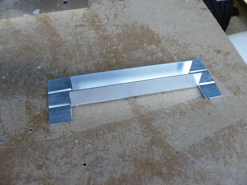
Here it is with the ends bent in to provide somewhere to rivet it.

Finally it was a case of finding the right height, making sure the bracket was level in both directions and then marking for the rivets. Once in place, the speedo sensor could be put in place and positioned so the head is between 3mm and 5mm from the magnet as they pass underneath. You can't really tell from the picture, but that is about 3mm.

Edit - April 2012: The above instructions are absolutely fine if you have an induction sensor but are not correct if you have a Hall Effect Sensor. These do not like magnets and should be set up to point at the bolt heads that hold the prop shaft to the diff. See the post 'Fixes and Tweaks' from April 2012 for more details of setting this up. Also, I have been told that the latest version of the Zero chassis has a bracket already welded on place for this sensor, so no need to make one up any more.
Whilst I was fitting sensors, or to be precise, senders, I decided to tackle the fuel gauge sender. First thing to do was to shorten the float arm. The Zero tank has a depth that ranges from 6 inches to 6.5 inches. I decided to shorten the arm so the range from top to bottom was 6 inches, so effectively allowing a sort of reserve tank. I used cable connectors as shown and applied thread lock to each of the screws.

I had already drilled 6 holes in the tank and hoovered out the swarf from the drilling. I then simply used self tapping screws to hold it all in position. Job done.

No comments:
Post a Comment