Saturday 11 June 2011

Centre Consul Sat Nav

We all have our objectives when we build these cars.  Some want them for a Sunday blast, some for track days and racing and others for touring.  I pretty much fall into the latter of these categories.  I am not saying that I won't go for Sunday blasts or even do the odd track day, but I think I will enjoy the trips away the most, especially getting on to the continent and with this in mind, I knew I was going to need a sat nav.  I had a Tom Tom XL that I bought about 3 years ago and it was sat in a drawer doing nothing, so I decided to use that.

It would be very easy to just use a sucker and stick it to the windscreen but my main road car has one built into the dash so I thought I would see if it would be possible to do the same with the Zero.  I decided that because of where the instruments will be on the main dash panel, it wouldn't be practical to fit it there so I looked at the other little centre consul that sits under the dash.  This is normally used for the horn, fog lamp switch and 12v socket but I decided to see if I could fit my sat nav behind this.

I didn't want to break the unit apart to fit it so it would need to sit in some sort of cradle and be visible through the panel.

First thing to do was to take some measurements of the unit and decide how large the opening would need to be.  I transferred these dimensions to the aluminium panel and cut it out.  I first drilled 4 hole near the corners and then used a jigsaw with a metal cutting blade to get some really good straight edges and corners.


Next was to mark out and cut the cradle that the sat nav was going to sit in.

This .....
 

.... became this ..... 

 ..... which was then folded in the right places to become this.  


Last thing to do was to use countersunk rivets to fix it in place on the back


Here it is with a trial fit of the sat nav.


Next thing to was to decide what button or switches I was going to have on the consul and where to position them.  The rear fog swith and horn button are the 2 that are normally fitted and also the auxillary 12v socket.  I thought about adding a starter button to match up with the 12v socket but there is a reason why I didn't.  I needed a method of being able to turn the sat nav on and off and the only way is to reach my hand round the top of the consul and press the button.  If there was a switch there, this would make this operation impossible and so the sat nav would be useless.

Once I had cut the holes for the switches and socket, all that remained was to cover it with vinyl.  This is quite fiddly and the finished item is by no means perfect, but it does the job.


Below you can see the view from behind.  You can just make out where I have cut the cradle lower on one side so I can get to the on off button and how a switch would get in the way.


This shows it better with sat nav installed.  I have put rubber round the edges of the metal and also some strips inside the cradle to stop it moving or worse still rattling.


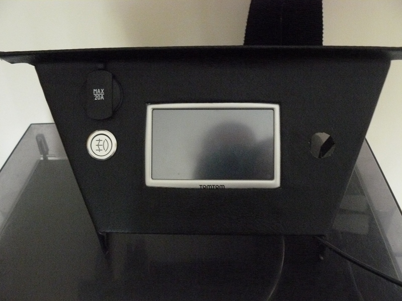
This is from the front with the 12v socket and rear fog light switch.


And finally, with the sat nav in place.  I just need to fit the horn button, which I am waiting for.


As for the power, I didn't really want the cable coming round from the nicely installed unit and plugging in the front, so I am adding a second 12v auxillary socket round the back that will be all hidden away, thus leaving the front socket for other things if requried.

So there we have it.  Built in sat nav .... well sort of!!!

Edit - April 2012: Since getting the car on the road, I have found that the Sat Nav can't pick up a GPS signal where it was.  See notes on this in the April 2012 post called 'Fixes and Tweaks'.  I say this to save anyone any time if they were thinking of doing this mod.

Tuesday 7 June 2011

Progress Pictures

The sun was sort of out today so I thought I would wheel the car out of the garage and take a couple of progress pictures.


At this point the scuttle is only sat on the chassis and not fixed to it, just so I could get a better idea of how it will look.


It is almost a real milestone when you can say the back of the car is almost complete.  There is still a bit of tidying up to do with the inner boot panels and the wiring, but it is getting there.

Sunday 5 June 2011

Front Brakes, Washer Bottle and Some Trimming

First job of the day was to sort out the front steering geometry.  The camber of the wheel (the angle at which it sits on the road), is set by the ball joint on the upper wishbone.  To set it correctly, there needs to be a distance of as near to 48mm as possible from the end of the wishbone to the middle of the ball joint.  The picture below shows the distance although the angle of the camera does make it look about 1mm out on each end, which it isn't.  Note also the rubber cover which is required for the IVA.  Best to fit this now so you don't have to take it all apart again later.


As mentioned in an earlier post, I had bought a set of fully reconditioned callipers from GBS but they had both been for the same side.  On a recent trip to get more parts, I swapped them over for a correct set.  Today I decided to fit them.  It is a simple process of putting some copper grease on the edges of the brake pads and fitting them and then bolting the calliper to the front upright, remembering to use some thread lock on the bolts.  Then I fitted the flexible brake pipe and put a large penny washer either side of the body panel where the brake pipe goes through it.  This will help to spread any load if the brake pipe moves around too much and will hopefully stop the body work from deforming.  Below you can see the calipers all fitted and you can just make out the flexible brake pipes now both exiting the calipers upwards.


The engine and gearbox should be next on the list, but I am not quite ready to start on this yet so I decided to find some other little jobs to keep me going for the day.  I decided I would try my hand at a bit of trimming.  The first thing I tried was the edge of the scuttle, where the dashboard sits.  This is to hide any aluminium and finish it off neatly.  I cut a piece of material (is it leatherette?  I don't know) and set about lining it all up to fit.   


It was all getting a bit cumbersome to do in one piece, so I decided to do the two sides first and then add the one piece across the top.  I used Bostik spray adheasive to glue it all.  Be warned, this stuff goes everywhere so you will need to cover up things you don't want glueing! Here you can see one of the side pieces glued in place before final trimming.


I repeated this on the other end and then used same process with the middle section.  It all looks a bit lumpy because of the rivetts that are used in the forming of the scuttle, but these get hidden with the final trim.  The bubble wrap was used to stop the scuttle and wiper assembly getting covered in glue.


Here is the finished job, all trimmed with the surplus material removed.  Not bad for a first effort. Most of it will be covered up with the dashboard and other trim.


Finally, I fitted the washer bottle.  This has a bracket with 2 bolts to hold it to the passenger footwell panel.  I replaced the normal nuts with locknuts.

Saturday 4 June 2011

Rear Lights

Today I thought I would tackle the rear lights.  First thing was a check of the IVA manual to see what requirements there are.  The main thing is to do with the positioning of the lights.  They have minimum and maximum heights from the ground and the lenses must be at 90 degrees to the floor, although I suspect the examiner will give you +/- 5 degrees on this.

So the first thing to do is apply plenty of masking tape to the area you are working on.  Now you can start to mark out where you think the light is going to go so it is at the right angle to the floor, is in the centre of the wing and is horizontal.  I spent quite a bit of time with tape measures and spirit levels to finally draw on the masking tape where I thought it was going to fit.  Then it is time to step back from the car and look at it by eye.  If you are happy with the positioning, then it is time to drill holes!  he light clusters need four for the bolts and one for the wires to go through.  Once drilled and fixed in place, the near side light cluster was fitted, but not yet wired in.


Time to move over and go through exactly the same process with the off side.  I really should have taken more photos of the process, but I didn't, so sorry about that.


With the two clusters in place, it was time to move on to the other 2 lights.  First was the number plate lamp.  A very simple process of 2 rivnuts and a hole for the wires, all of which are already cut out for you on the rear panel (well they were on mine).

I referred to the GBS ZERO Chassis Harness PDF document that I had sent to me as this shows all the wiring and what connects where.  The Number plate lamp was simple as it was just 2 wires, one either end of the bulb.  It doesn't look much on its own!! 


Nest are the other 2 warning lamps, the fog lamp and the reversing lamp.  Now you have 2 choices here on how to mount these.  One way is to use the metal brackets that come with the lamps and rivet them under the rear panel and fix the lamps on to those.  This will do the job but may not look too good.  The other option is to fix them to the rear panel and this is where you have to modify the lamp unit.  The IVA manual says that the lamp must be at 90 degrees to the road and if you fit the unit straight to the rear panel, because the rear panel is angled, the lamps will also be angles upwards.  the solution is to cut the black box par of the lamp so it sits square.  The top of the unit is 42mm deep and the bottom needs to be 32mm deep, with the appropriate angled cut down each side.  This way when it is offered up to the rear panel, it sits at the right angle.  Once cut, you will need to add some trim to hide any rough edges.  You must make sure the hole where the wire comes through is at the top when you make the cut.

I then chose to use the fitting bolts that came with the lamp although you could use rivnuts and bolts if you want.

Wiring was again a simple task of following the PDF document and connecting the right wires.  I just need to get some bulbs for these lamps. 

This is the finished job before wiring in the light clusters.


So now the light clusters.  This is fairly straight forward and involves joining the right wires on the harness to the wires on the light cluster.  Again, all this was very well laid out on the wiring diagram.

All in all, it wasn't the quickest of jobs to do, but if you work through it methodically, it is easy enough to do.  Of course I can't check any thing at the moment as I don't have a battery fitted and there is another part of the loom to be fitted for some of the switches. 

Friday 3 June 2011

Rear Arches

My target for today was to get the rear wheel arches fitted.  First thing to do was to lay out the arch and decide how many fastenings to use.  I came up 3 inches from the bottom edge of the arch, front and back, and then spaced out at between 6 and 7 inches to give me a final total of 7 fixings.  Looking at some images I had taken at the factory, this seemed about right.  I also measured in 1 inch from the out edge to keep everything neat.


Once these were marked out, I drilled 6mm holes for the M6 x 20 hex bolts to fit through.  I also used large M6 repair washers to help spread the load out.  Once drilled, the arch can be offered up to the car.  This is quite awkward and is best done initially with the wheel in place.  The lower edge of the front of the arch should sit flush with the bottom of the chassis rail and the lower edge of the rear of the arch should do the same with the bottom of the rear panel.  I used some masking tape on the arch to then mark on the body where the arch should sit.

Next, remove the wheel so you can get access under the arch.  Offer the arch up again try and mark through the holes on to the body where the rivnuts need to be.  This is a very fiddly job, especially if you try and do it single handed (like I did!!).  If you have 1 or even 2 helpers to hold things in place it will help.  It would also help to do the job out side where you have a bit more room around the car and can stand back and line the arch up by eye.  The method I employed was to drillthe 2 lowest holes at 6mm and used 2 M6 .x 20 hex bolts to hold the arch in place whilst I marked the other holes.

Anyway, once the holes are marked, they can be drilled out to fit the rivnuts and you end up with a panel that looks a little bit like this.


Next job to tackle is the tadpole trim that sits between the arch and the bodywork.  This will need a lot of V cuts putting it it so it goes round the curve and also cut out where the rivnuts are.  Once this is done, the arch can be fitted losely, to allow for the trim to be slotted in.  Once the trim is fitted, the whole thing can be tightened up.


Repeat the whole process for the other side and you end up with the following result.


And here is a view from the rear.  It may look a bit lop sided but I think that is more the photographer and not the car!!


I still have the lights to fit but the rear end is now getting close to being completed.

The final task I did today was to remove the clutch from the engine so that I could fit the spigott bearing.  This has to be fitted to the Zetec engine to match up with a rear wheel drive gearbox, in my case, the MT75.  This was straight forward although the spigott bearing does have to be taped in with a hammer.

Next time I will move on to the front of the car.

Thursday 2 June 2011

Rear Panel Final Fit

The time was right to finally get round to fitting the rear panel.  I am sure other builders have fitted them a lot quicker than me, but I wanted to make sure it was right.  I am still not sure it is 100% right, but it is too late now!!

Final couple of things to do before the final fit.  First was a bit of wiring whilst it was easy to get to.  This was the fuel pump to join it to the loom.  Next was the boot panels.  I had been to the factory earlier in the week to get some more parts and whilst I was there, found out that the flat panel for the boot I had got had been superseded with a frame and inspection panel.  This is a much neater arrangement.  First thing was to drill and fit the frame panel.  Some Sikaflex and rivets later, it looked like this.


Next job was the side panels.  I had been unsure as to whether the top lip went over or under the chassis frame.  My factory trip confirmed that they were designed to go under, so under they went.  Later chassis may have these panels already welded in place.  Again copious amounts of Sikaflex and some rivets were used to hold these in place.


Finally, I got round to fitting the rear panel.  I had trial fitted it and removed it probably half a dozen times so it was time to go for it.  A final dry fit to drill some holes for rivets in the side rails and also under the panel under the back of the car and it time to clean it all up and, again, add copious amounts of Sikaflex to the chassis rails where the panel will be riveted.

Once that was done it was all offered in to place.  I did start to panic a little here, worrying that the Sikaflex might go off quite quickly, but I actually had plenty of time to put it all in place.  I started by securing the rear stays and then lining up all the rivet holes I had just drilled.  Once these were all lined up, it was time to start riveting.  I started under the back of the car and this took a bit of jiggery pokery to line up but it got there in the end.  I then finished the rivets on the side panels at the front of the rear panel.

Next job was to add some beading round the inner edge of the U shape former that makes up the top of the boot and finally work my way over the crescent to finish off the wheel arch shape.


This is a view of the inside of the nearside panel.  A reasonably neat job that will get covered in carpet at some point.  You can see I have started to cut some carpet and have just dry fitted the rear panel to see what it looks like.  I have a roll of carpet to cut it all out from but I have found out that GBS now do a laser cut carpet set that will include all the panels, including the boot.  I will probaly buy pne of those as it will save me hours of measuring, cutting, triming etc.


This is a view of the rear panel finally finished and bonded on place.  Too late to change it now!!! 

The final job for today was to fit the fuel filler cap and pipe.  Very simple to do but very fiddly to get the small washers and nuts on the bolts.


And here is the filler cap.  This is a vented cap and can only be opened and locked with a key.    This way it meets IVA requirements.