Wednesday, 9 November 2011

Fuel Pump, Tunnel Top and Tunnel Panel

Started today by connecting up the high pressure fuel pump.  It is a simple 2 wire job but beware, the pump has a very definite positive and negative connection, even the posts, electrical connectors, nuts and washers are different sizes so you can't wire them the wrong way round.  One is 7mm the other 8mm.  Here is the finished job.


I then cable tied the surplus wires to the brake pipes at the side of the car to keep it all neat and tidy.

Next job was to move on to the top of the tunnel.  As mentioned in the last post, I am going to include an iPod so I can have music as I drive (Yes I know I said this would be much later ... like after IVA later, but I couldn't wait).  The first thing to do was to decide where to fit the iPod.  I bought an iPod holder with the intention of fitting it to the top of the tunnel (I had considered other places but none would be in easy reach).  When I looked at it, it just didn't look right.  OK, so it would mean the iPod could easily be removed, but it just looked .... well, sort of "icky" ... so I decided it had to be built in to the tunnel top, the same as I had built in the Sat Nav to the centre consul.

Anyway, after getting the right measurements, a hole was cut.  Next job was to cover the panel.  I am starting to get used to doing this now and I think I have done a reasonable job.


Here it is from underneath.  I just need to fabricate the bracket to hold the iPod in place and then bond that to the panel.
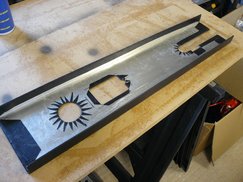

What I did next was to run the power cable for the iPod from behind the centre consul where the 12v supply is, to about half way down the tunnel, securing it with cable ties.  I did the same with a headphone extension lead, but running this to the back of the tunnel, leaving enough hanging loose behind the driver's seat.  I can then plug my earphones into this socket, keeping everything neat and tidy.

Final job of the day was to fit the nearside tunnel panel.  First I made sure I had done every thing I had to where good access was required.  I checked the sensor magnets and the Araldite and it was a good job I did.  The magnet sitting on top of the diff flange was OK, but the one underneath had dripped, causing a sort of stalactite.  I trimmed this off with a Stanley knife so it was flush with the top of the magnet.  The only other thing I could need access for would be the bolts on the drive shaft, front and rear.  These have all been torqued up correctly and also had thread lock applied for extra security.

Once I was happy with all this, the next job was to prepare the panel for fitting.  The panel was already drilled ready, as was the chassis, so I simply roughed up the fixing points and applied some Sikalex (nasty stuff - remember to wear gloves!).  Final job was to then simply rivet it all in to place.  Disaster!!  The rivet gun appears to have given up the ghost!  It will fix the rivet but not then release the pin, meaning you can't get the next rivet in.  A quick trip to Tool Station and £8.75 later, I have a new rivet gun.  Bugger .... that doesn't work either ... same issue.  It must be the rivets.  After playing about, I finally found I could do one rivet, pull the pin back in to the gun a bit and push the next rivet in, which had the effect of pushing the old pin out.  Much more time consuming, but it got the job done.

I finally had to put 2 rivets in to hold the speedo sensor bracket.  I had applied lots of Sikaflex so it could just be glued but I thought I would try and rivet it as well.  I had already put 2 holes in the bracket, I just had to put 2 holes on the panel to match them.  I measured the depth and lined up the drill by eye.  Bulls eye!! First one was spot on.  I riveted that.  Second one wasn't as easy, but I still managed to line the holes up and a second rivet was fitted.  That bracket isn't going anywhere!!


Now this is all done, I can move on to fitting the carpets which will really make the car look like it is moving forward.  Only real problem is that I really need to get the paint work done so I can start putting the rest of the car together.

Tuesday, 8 November 2011

Wiring, Fuel Lines and Sensors

I have been having a bit of bother with some of the wiring on the car.  As some of you may know, well those paying attention, I have gone for the plug and play wiring loom for my Zero.  This has also meant purchasing a sub loom for the instruments and also one for the lower panel with the horn button, fog light and 12v socket.  This is also where I have mounted my Sat Nav system.  Anyway, after a few e-mails with the factory and some help from a member of the RHOCar forum (who I am 99.99% certain works for GBS .... nudge, nudge, wink, wink, say no more!!) I finally got it all wired in.  Since taking the picture below, the single 12v socket has been replaced by a double so that I have a spare socket to run an iPod from.  More about that later, a lot later, like after the IVA type of later.  Anyway, here it is.


Next thing to tackle was the leads from the battery.  I wanted them to be neat and tidy and remembered seeing the leads being fed through the dash on a factory car.  A quick confirmation from my RHOCaR buddy, and this is what I have done.


Here they are just sitting on the battery, not connected, just to show how neat it is.


It has meant I had to slightly re-position the Emerald ECU, but that was simple to do, time consuming, but simple.

As I am not ready to start the final wiring at this point, I moved on to some of the fuel system.  I sorted all the fuel pipes coming and going to the swirl pot.  I just need to cable tie them all together for neatness, but I ran out of cable ties!


I then did the final run from the swirl pot to the fuel regulator, which simply bolted on to the bracket as seen below.


Next job was to fit the speedo sensor.  This comes in 2 parts, well 3, if you consider there are 2 magnets!  The first is the sensor itself, which I think is known as an induction sensor and the second is the magnets.  The first job is to position 2 magnets on some part of the car that is turning when the car is moving, I chose the differential flange.  The magnets are pretty strong and stick well to the flange.  Here is one in position, the other is 180 degrees opposite.


Although the magnet holds itself in place, you also have to Araldite them on so that they don't move or fall off, rendering the speedo useless.  Here is one I prepared earlier.


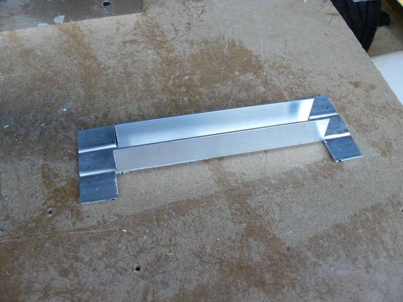
Unlike some kits that come with a nice bracket already welded in place, I had to make one up.  I could have bought one from GBS but decided to have a go myself.  This is a piece of 3 sided box aluminium.  I took a measurement across where the sensor has to sit and then knocked off 5mm to allow for the outside edge to be bent in.  I also took into consideration the taper on the rear of the tunnel where this sits.


Here it is with the ends bent in to provide somewhere to rivet it.


Finally it was a case of finding the right height, making sure the bracket was level in both directions and then marking for the rivets.  Once in place, the speedo sensor could be put in place and positioned so the head is between 3mm and 5mm from the magnet as they pass underneath.  You can't really tell from the picture, but that is about 3mm.


Edit - April 2012:  The above instructions are absolutely fine if you have an induction sensor but are not correct if you have a Hall Effect Sensor.  These do not like magnets and should be set up to point at the bolt heads that hold the prop shaft to the diff.  See the post 'Fixes and Tweaks' from April 2012 for more details of setting this up.  Also, I have been told that the latest version of the Zero chassis has a bracket already welded on place for this sensor, so no need to make one up any more.

Whilst I was fitting sensors, or to be precise, senders, I decided to tackle the fuel gauge sender.  First thing to do was to shorten the float arm.  The Zero tank has a depth that ranges from 6 inches to 6.5 inches.  I decided to shorten the arm so the range from top to bottom was 6 inches, so effectively allowing a sort of reserve tank.  I used cable connectors as shown and applied thread lock to each of the screws.


I had already drilled 6 holes in the tank and hoovered out the swarf from the drilling.  I then simply used self tapping screws to hold it all in position.  Job done.


Monday, 31 October 2011

Fitting the Alternator

Now the engine is in, I can move on to the ancillaries.  I am waiting on some bolts to fit the starter motor so I thought I would tackle the alternator.

Here is a picture of all the things you get in the alternator kit.


It all looks very good and very complete, but there are no instructions to tell you where things go, what bolts are for what, where the washers go etc.  As with a lot of things, you have to work it all out for yourself.    First thing to do was to paint the brackets as these had not been powder coated, which is a shame considering the cost of the kit.  Anyway, I had a look at all the photos I had taken at the factory of various cars and was able to work out where the first bracket went.  1 bolt at the front and 2 at the side.  I used 2 washers as spacers but I now think that the 2 hole bracket is probably meant to be a spacer.


The upper bracket on the off side then fits with a ..... missing bolt!  All those bolts and washers in the kit, but not this one!  Good job I had the right size in one of my selection boxes.

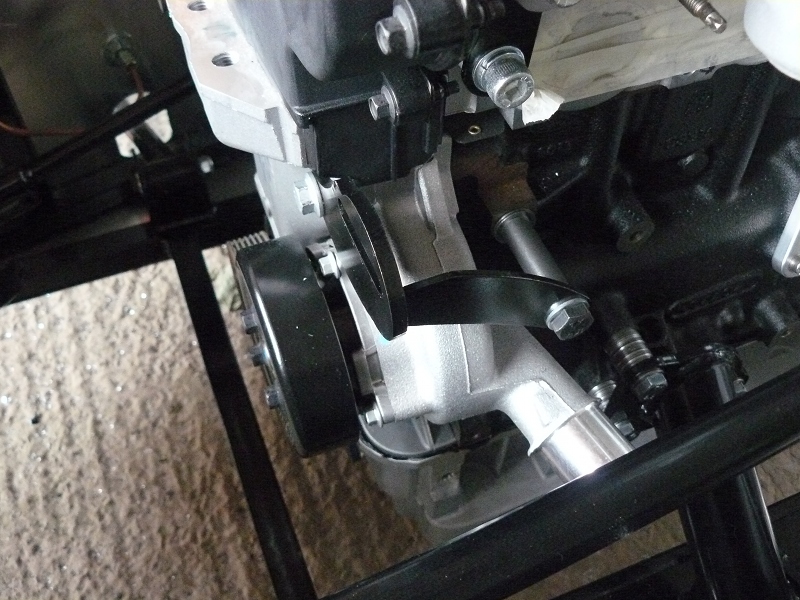
The alternator then fits with a bolt and washers to make up a spacer on the bottom bracket.  A simple bolt then secures it through the upper bracket.  It is important at this stage to make sure the alternator wheel is square to the other wheels the belt will go around.  At first, mine was slightly out of alignment.  A couple of tweaks on both brackets and it sat square.


Here is the view from the back.


On the near side the bracket mounts to the front of the block using an existing bolt and then with a couple of washers and a spacer tube.


Here it is from the front.


Next thing to add is the adjuster wheel


And finally, the belt can be added.


I also had a bit of spare time so cut the hole out for the gear lever.


Saturday, 29 October 2011

Sump and Engine Fitting

Today was the day to finally get the new sump and the engine fitted.  My son-in-law, Stuart,  had agreed to come and help me and believe me, this is not a one man job!

First job of the day, put the kettle on!  Whilst drinking said cuppa, read through the Raceline sump fitting instructions.  It all seems straight forward until they start talking about cutting bearing cap retaining bolts.  I didn't like the sound of that but, as it happens, this particular engine didn't need it to happen.  I suspect that the instruction sheets have to cover several different variations of Zetec engine and these bits related to a different model.  Although my engine is 'new' it was built in 2004!  Ford intended to use them in the Focus but changed plans to use the Duratec instead, resulting in a few thousand 'spare' engines.  Many of these have found their way in to kit cars.

Anyway, first job of the day was to drain the oil out of the old sump to prevent any mess later.


Next, put together the Raceline sump.  This really is a nice bit of kit.  The instructions are simple to follow.  The oil pick up pipe will need quite a bit of pursuasion to fit but it does go.  In no time you will find you have fitted the pick up pipe and fitted the tray before you remembered to take a photo.  Oh well, never mind.  I also forgot to take one with the windage tray fitted but it is not very exciting to be honest.


Next job was to remove the old sump.  Now you can't simply undo the bolts to the aluminium part of the sump and expect it to come off.  You have the remove the black tin part first.  The reason for this is the oil pick up pipe is bolted on and it has to be removed before the cast aluminium part can come off.  We spent quite a while trying to figure this part out.  This is the fixing point with the pick up pipe now removed.


The next job was to place the gasket in place and apply a bead of silicone all around the outside edge of the new sump.  This will help the whole thing seal against oil leaks (I hope!!).  The new sump can then be offered up to the engine and bolted in place, making sure the rear of the sump lines up with the rear or the engine block, which it appeared to do do automatically.  Also making sure the sealing washer and O rings stay in place.  I watch carefully and I am prtty sure they stayed where they should.  Too late now!!

Edit: 3rd December.  A fellow forumite on RHOCaR, Martin Smith, who is also building a Zero, asked me if I had fitted a spigot bearing to the engine.  I had, but forgot to add it to the blog.  This seems the most appropriate place to add the pictures and details.

The spigot bearing is required when you are fitting a rear wheel drive gearbox like the Type 9 or the MT75 to a normally transverse mounted, front wheel drive engine, like the Zetec.


You will need to remove the clutch to be able to fit the bearing.


You have to tap the bearing in place with a hammer and some form of drift, preferably wood, so the bearing doesn't deform.  You are also advised to fit it the right way round, with the bearing ends pointing inwards.  You will see what I mean when you look at the bearing.

Here it is, bearing fitted and clutch back in place.


Now back to the engine fitting.

Once the sump was fitted and tightened down, it is time to mate the gearbox to the engine.  First problem we encountered was that the clutch plate wasn't aligned correctly.  A quick alignment and this time the gearbox fitted in place.  A couple of the supplied bolts had to be cut down a little but other than that it was uneventful.  The clutch actuating arm seemed very loose until I realised I was pulling it the wrong way.  When pulled the right way, there was the full pressure I would expect.


The engine mounts can be fitted next, or so I thought.  You can't fit both parts or the whole assembly will be too wide to fit in the engine bay due to the chassis members.  It would possibly have been just as easy to fit the engine mounts once the engine was in the car.

Hear is the nearside, which needs packing out with a large number of washers, due to a lug on the engine block.  I think the factory now provides some proper spacers.  You can certainly get the dimensions to cut your own if you want.  I had to use washers, I didn't have a choice.


This is the off side, no issues fitting this side.


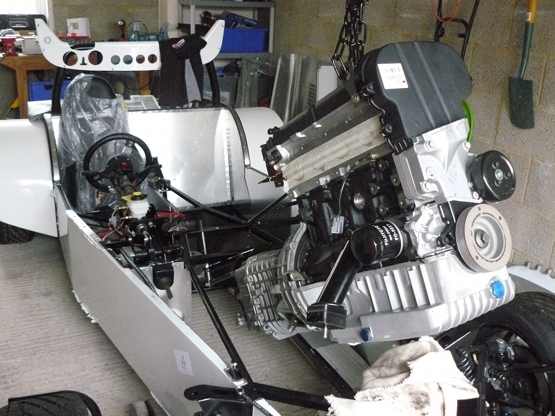
This it was time to hoist the engine high and start the gentle process of making it fit.  It is a case of forward and lower a bit at a time with one person pushing and the other guiding the quick shift under the chassis rails. You just have to take your time here.


Here it is a bit further in.


And finally lowered in place.


Next step is to line up the engine in to the centre of the chassis.  I measured and drew a centre line on one of the cross members and then used a square to find the centre point on the pulley.  Although not shown in this picture, I also put a piece of tape across the pulley and found the centre point to line up against.  The final line up is spot on.


Here it is from the rear.


Final thing to do is to bolt the engine mounts to the chassis plates.  We drilled the 8 holes and tried to fit the nuts to the bolts by feeding them in from the sides.  I could tell that this wasn't going to work.  To be able to easily access all of this, the engine must be fitted before the side panels are fitted.  Again, in a proper manual, the build order could be established and I would say to anyone that fitting hte engine and gearbox would be a lot easier without the side panels fitted.  Just my 2 penny's worth.

Anyway, back to fitting hte engine mounts, we ended up drilling through the aluminium underneath and then enlarging the holes so the bolt and a socket could pass up through them.  I then held a socket on the bolt, whilst Stuart did up the bolt.  Again, this is something that I couldn't have easily done on my own.  I will need to cover these holes with an aluminium plate of some sort, but that will be easy enough to do.

All I can say is that I am glad it is all in now, but I ache in places that I didn't know I had places!!

Sunday, 23 October 2011

More Pottering in the Garage

Been a sort of 'bitty' day today.  I have done a few little things but nothing major.

First job was to fit the cooling fan to the radiator.  No instructions in the box, but it seems pretty straightforward.  Here it is fitted, but not wired up yet.


And here it is with the nose cone fitted.  There is clearance all round but it is measured in millimetres!! 

Next I moved on to fitting the seat runners to the seats.  Once you have figured out where the mounting points are, this is a nice simple job.


Next thing to do is to mark out where the sear runners are going to fit to the chassis.  I figured that the furthest point back has the runners as far forward as they can go.  I put the seat in and marked the front holes.  The using the spare runner from the other seat, I was able to mark the rear holes as well.  With the holes drilled, I made sure that the seat runners would fit.  It was all OK so I went ahead and repeated the process for the other side.  I haven't fitted the seats in yet as I need to fit the carpet first.


Next I moved on to the dashboard and the 'T' shaped warning light module I bought from the Exeter show.  Guess what, it comes without fitting instructions or a wiring diagram!!


Fitting is straightforward.  You need to drill 8mm holes for the lights to shine through and 3.2mm holes for the screws to go through to hold it to the front panel, which need to be counter sunk. 

It then looks like this from the back.  This needs to pass through the fibreglass dash panel so a similar T shaped hole has to be cut in the fibre glass.  To be honest, the hole I cut isn't the prettiest, but it does the job and will be hidden by the stainless instrument surround.


Whilst I was working with the dashboard, I decided to see if the instruments would fit.  After a bit of tidying up with the jigsaw, I was able to fit the gauges in place.  I think it is looking pretty smart.  Remember that the dash won't be that colour when finished, although it doesn't look that bad in white!


Speedo and tacho.


And the view from the back.


I have purchased the correct plug and play loom from GBS for the instruments, but I need to get hold of a wiring diagram so I know what to plug where.  I am hoping it won't be too complicated to sort out.

So there is another weekend gone by.  Next weekend ..... the engine!!