Sunday, 27 March 2011

Rear Crescent Infils

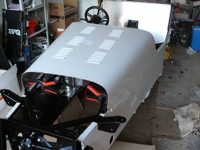
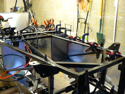
The next job I decided to tackle was the rear crescent infill panels.  The first part of the process was to de-burr the edges of the aluminium where the laser cutting process had left lots of rough edges.  A good sanding block and a set of various files are needed to do this and it is always handy to have a pack of plasters!! Yes, I managed to cut myself ... again!!

Anyway, once I was bandaged up, I was ready to move on to the next step, bending the tabs over.  This is a simple process but should not be rushed.  I took each tab in turn and clamped a right angle off-cut of aluminium to bend against, and clamped it together.  It was then a simple case of using 2 thumbs to bend the tab so you bend it square to the infill panel.


The whole job takes about 15 to 20 minutes and the end result looks like this.


The next stage is to line up the panel.  This is where a bit of lateral thinking is required.  Where should the panel sit?  Well I looked at the where the rear panel would sit and this runs over the flat part of the chassis rail where the roll bar sits so I took a flat edge and clamped that and that then gave me a guide as to where the curve of the crescent should be. 


Once that is lined up, it is a simple case of clamping it in place as best you can and then following the same process as fitting the other panels.  Mark the panel where the rails are, remove the panel, draw a centre line, mark off 50mm points (2 inches), centre punch, drill the holes, de-burr, offer up the panel, drill a couple of guide holes into the chassis rail, fix with self tapping screws to hold in position, drill the rest of the holes, remove panel and clean debris, rough up the contact points to get a good bonding surface and apply a bead of Sikaflax or similar.


Finally put the panel back in place and add all your rivets, in this case I used 33 per side.


And the end result is a very neat inner panel that is very securly fixed.


Finally, repeat the process for the other side.


Saturday, 26 March 2011

Rear Brakes

Following on from the front suspension I decided to move to the back of the car and fit the rear brakes.  When I picked up my donor pack, the drum brakes looked pretty nasty so I have opted to fit disc brakes on the rear of the car.  This way I know all the parts are new.

The whole process was pretty straight forward once I had worked out how the brake pads were fitted!!  The only thing to remember to do was to apply some Loctite to the bolts that hold the calipers to the bracket.  Once both calipers and discs were fitted, it was a simple task of fitting the hand brake cable and the flexible brake pipe.  It is all ready now to have the fluid added and for the brakes to be bled, but I can't do that until the front brakes are fitted.  I am waiting on the factory to get a new supply of front brake discs and calipers before I can do that.

Front Off Side Suspension

So, I have taken another week off work to do some more work on the car and the first thing on the agenda is to fit the front suspension.  This is a fairly straight forward task.  The first thing to do is to clean out all the mounting points where the bolts go through as these will be slightly reduced by the powder coating.  You have 4 options for doing this, a 10mm reamer, a round file, a Dremel type drill with appropriate sanding bit or a 10mm drill bit.  As I don't have a 10mm reamer, I used a combination of the other 3.  Took a while but it has to be done.

First job was to fix the lower ball joint to the lower wishbone.  For some reason this mounts underneath the wishbone and not on top, I suspect it is to do with the steering geometry in some way shape or form, but I don't know what it is!!  Next, the lower wishbone can be fitted.  The mounting points will need packing out with washers so the wishbone is nice and snug.

Edit - April 2012: Following the IVA check at the factory, I discovered that I used the wrong sized washers for packing the suspension.  In the image below (of the upper shock mounting) you can see that the washers are a smaller diameter than the neoprene bush.  They must be the same size or bigger to prevent the bushes from wearing out prematurely.  I have got to re-build my suspension at some point soon to rectify this.

The upper wishbone is next, making sure you get the orientation right.  This is also the time to fit the upper ball joint and this has to be wound in so the distance between the end of the wishbone arm and the centre of the top of the ball joint is 43mm (well I am pretty sure that is what I was told by the factory).  Before you fit this, make sure you add some IVA cover so you don't have to take it off again later.

Next is the wheel hub.  This simply sits over the lower ball joint on the bottom, but the top is a different affair.  Here you need to add the front mudguard mounting bracket which is attached to a mushroom piece that fits in to the top of the wheel hub.  The upper steering ball joint fits into that  mushroom piece and it all bolts together.  

Finally, the shock absorber/damper, whatever you want to call it, can be fitted.  Like the wishbones, this will need packing with washers to line it up right.  You can see this in the picture.


The whole process takes a few hours of fiddling about and is not that easy to describe but the picture below, showing the nearly finished set up, should explain it a little better.  I still need to add the steering rack and a pinch bolt but it is not far off.

  
I wanted to move on and do the near side but I was missing 2 longer suspension bolts from the original pack I was given.  I have asked the factory to send me 2 more, but I am still waiting on them.

Sunday, 13 March 2011

Almost Back to Where I Was

This weekend I started off by re-fitting the rear suspension and adding some extra washers in where required.  This followed my visit to the GBS open day where I was able to see how they fit these things and was able to see that I hadn't quite got it right.  Still, easy to fix now before all the bodywork is fitted.

I also refitted the diff and drive shafts now they have been re-furbished.  It was all a bit fiddly but it is now in.  I have used Loctite on bolts as required so it should all be pretty secure.  Once this was done I was able to re-fit the wiring loom, hand brake cable and fuel pipes and used a couple of 'P' clips to hold things in place.  The rest will be held by cable ties.


This was the main thing I wanted to achieve this weekend but I had a bit of time over so I thought I would dry fit a few things just to see how they fitted.  The first was the bonnet.  It looks pretty good but it will take a little bit of tweaking when the time comes.


I also trial fitted the steering wheel.  I resisted the option to get in the car and make 'brum brum' noises at this point!!


Finally, I dry fitted the panels that will line the boot to make that a usable storage area.  It will also get carpeted so should look reasonable.


Although the fuel tank looks like it is fitted in the picture above, it actually isn't and that will be one of the next things to do.  Some of the plumbing is already done but a little more will be required to finish the job.  I can then move on to the front end and start fitting the front suspension and I am getting close to a rolling chassis.  I need to think about wheels next and decide what to go for.  Still, that is a question for another day.

Sunday, 6 March 2011

Update and GBS Open Day

Well, not a lot to report.  It has been pretty cold out in the garage for the last few weeks so I have not done much at all.  I re-plumbed in swirl pot with the right size fuel pipe and also fitted the steering rack and steering column.

I have finally got the diff and drive shafts back from being checked over and re-furbed.  We had to get a new back plate as in trying to get the filler plug out, the plate cracked.  Anyway, it is now fitted with a new back plate, with a new plug and the diff is all ready to go back in.  The drive shafts have new boots so all is good.

The only other main thing I have done is to get the car down from the trellis stands to axle stands whilst it is still light enough for me and the son-in-law to lift it down.  I know some people are lucky enough to have engine hoists or block and tackle in the roof of the garage, but I don't, so it has to come down using man power.  It does mean that it will be a bit harder to work on, but never mind.  I think I need a low stool to sit on that has casters on it so I can move around whilst doing things to the car.

Saturday 5th March - Great British Sportscars (GBS) held an open day to celebrate 1 year since the new directors took over.  It was an overcast day and rained or drizzled a lot.  About a dozen people braved it and turned up in their Robin Hood 2Bs and there was 1 Zero.  I had chance to have another look around at some part completed cars and take loads of photos as a guidance.  I also got to talk to some fellow Zero builders and compare notes as to where we were in our respective builds.  I also picked up a few parts, not that I am ready for them yet, but it seemed silly to go all that way and not pick up something.

When I first got the kit, I was in a rush to start getting things on the car and now, when I look at other cars, I see I haven't quite got things right.  Accordingly, a few parts will have to come off and be re-fitted, but this is no real issue and it is better that I get it right now, when the parts are easy to get at, than for them to be picked up at IVA stage!!

Saturday, 12 February 2011

Offside Panel Fitting

Not a lot to report this week.  The diff and drive shafts (half shafts) are still with the local garage for new boots and seals.  The main problem he is having is getting the correct boots and seals.  When ordering, the parts suppliers nearly always want a chassis number or registration number, neither of which I have as I got my donor pack from GBS and didn't get a V5 document.  Anyway, he now has the right parts so I should be able to get them back sometime next week with a view to fitting it all back in next weekend.  It's not a problem as I don't have a lot of time to spend in the garage this weekend anyway.

What I did have the time for was to fit the off side panel to the chassis.  It was exactly the same process as fitting the near side panel, which I described in my last post.  So here it is.


The other thing I did was to fit the fuel pipe that connects from the bottom of the swirl pot to the high pressure fules pump.


You can also see from the image above, the number of clamps that are used when fitting the side panel.  I would have used more if I had had more!!

Sunday, 6 February 2011

Nearside Panel Fitting

As I mentioned in the last post, I had to remove the drive shatfs and diff to inspect them.  I decided to take them to a local garage to get them re-furbished.  They are going to put  new drive shaft boots on and also new bearing and seals on the diff, if required.  Best to have it all done now and not later when it is all more difficult to get at.  It would not be fun to fail the IVA on leaking drive shafts boots!

Well I have not got them back yet so I had to move on to something else.  First off was a little bit of electrical work.  As mentioned elsewhere, I have bought the factory loom for ease but it doesn't just plug in to the ignition block that come off the Sierra.  I needed to fit a different block to join to the loom and this was a simple case of cutting some wires, soldering some new spade connectors on to the wires and putting them in a block to connect to the factory loom.


I also had a look at doing some of the plumbing for the fuel runs but realised that the fuel pipe supplied with the kit was OK for 90% of the runs but not for the one from the bottom output of the swirl pot to the input of the high pressure fuel pump.  I am going to have to get some more to sort that out.

After doing this I moved on to the left hand side panel.  The panel had been on and off the car, dry fitting it several times and there was nothing left to do but to get on and fit it.  I put the panel on for one last dry fit, found a few places it needed a bit of tidying and trimming and took care of those.  Next was to mark up and drill the few rivets I was going to apply.  Now I have seen cars where the builder has possibly used 100 or more rivets on each side panel, but I was going to use as few as possible.  I had been told by the factory that they only bond the side panels on and put in a few token rivets, more to keep the IVA inspector happy then anything else.  I figured that if it was good enough for the factory, it was good enough for me.  Having said that, I have already put in more than them and I may put a few more in yet!!

Anyway, next thing to do was rub down the surfaces to be bonded to get a key for the glue to stick to.  Once done, I ran a bead of sealant/glue down all the surfaces that contact would be made.  Finally, I had no excuses left, the panel was ready to be fitted.  I slowly maneuvered it in to place and then set about riveting and clamping everything up.  I had bought some extra clamps for the job and used every clamp I had and some box tubing to help apply some pressure.


Here is another view from the inside after more clamps had been applied.


All I can do now is wait for it to go off.  Overnight would be fine, but mine will get left until next weekend, only because I am at work during the week, so it should be well and truly fixed.  I am going to be really stuffed if it needs to come off for any reason as I don't think it is going anywhere!!