Tuesday, 7 February 2012

Bleeding the Brakes and a Colour Taster

First bleeding the brakes.  Now as I knew that I would most likely be on my own to do this, I purchased a kit that you fit on to the fluid reservoir and then apply pressure from one of the tyres.  The system actually works really well.  The pressure pushes the fluid through the pipes and within a very short time, the front brakes were sorted.

On to the rears and this is where the fun starts.  The zero uses what I think are Cosworth rear callipers and they are actually fitted upside down and this means that to bleed them properly, avoiding air locks, you have to remove the callipers from the car, but keeping them connected, if that makes sense.  So far so good and the process of bleeding the brakes was uneventful, like the front brakes.

The problem for me came when I tried to fit the callipers and brake pads back on to the car.  The off side fitted without a hitch, the nearside was a complete bar steward!!  I think the pressure had pushed the piston out a couple of millimetres and that was enough to stop it fitting.  Now I don't possess the various tools required to push pistons back in so I had to resort to drastic measures.  Now I must say that I am not proud of what I have done, but needs must when the devil farts in your face!!  Just so I could get the calliper back on, I ground down the pads.  The calliper is back on but it will need new pads fitting before it can go in for the IVA and the stringent brake test.  I will get GBS to do this for me when I take the car in as I am sure they have the required tools to do the job properly.

Now on to better things.  If you have been following the blog, you may remember me saying that I was going to have the car painted.  Well, it wasn't practical at this stage to try and get the whole car to the paint shop, but I was able to take in all the removable panels and I had a call today from my son in law to say that the panels were ready to be collected.

Naturally, I duly obliged and they are now home with me.  I am keeping them in the flat for a few days to fully harden and I will do a separate post to give the full details.  However, my friend Hammy, another Zero builder, was after knowing what the colour was I had chosen so here is a taster.


The colour is Ford Imperial Blue and I think it looks the dog's danglies.

Monday, 6 February 2012

Front Indicators

Now much has been said about the front indicators on the standard Zero and the fact  that you need to add extensions to them so they pass the IVA.  Frankly, they are a means to an end.  It all comes back to building the car to pass the IVA.  After that, do what you like.  This is how I sorted them out.

In the kit, you get the indicator and a piece of metal that needs bending to form the extension.  Make sure you also get the nuts fro the indicators as they are a strange thread. What you will also need is something to cover the extension.  What I bought were Landrover shock absorber covers from the bay of E, although I am sure there are lots of other suitable alternatives.  The other bits you will need are 10mm by 35mm threaded tubes.  Again I got these from the bay of E from a lighting shop as these are used in the manufacture of side lamps etc.  The final thing you can see is an aluminium disc that I cut from an off cut.  This is to hold the end of the rubber cover firmly in place.


First job was to bend the extensions.  Once done I fitted a bolt tot he threaded tube, and then araldited the extension to the disk with the tube in place.  Once it was all dry, I sprayed it with black Hamerite, just to protect it.  You can just make out a small hole above the main hole in the end of the bracket.  This is for a small lug on the indicator to stop it spinning round.


Here are the bits all laid out ready to go together.


Here you can see the nut and lock washer inside.  It is is all a bit fiddly to do, but with patience, it does all go together OK.


And here is a finished item and the other waiting to go together.


Finally, here it is fitted to the nose cone.  Personally, I don't think it looks that bad.


Here it is from the inside.  I have some larger washers for when I fit it permanently, just to spread the load out a bit.


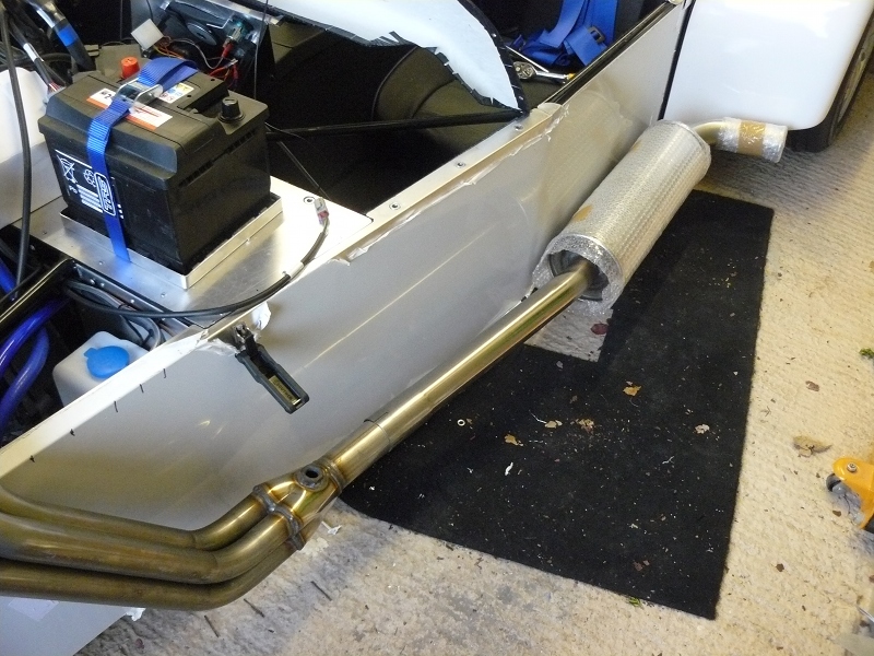
Last job of the day was to see what the exhaust would look like.  I still have the Catalytic Converter fit.


Following this, I took all the panels off the car ready to go off to the body shop to be professionally sprayed in  .........  well you will just have to wait and see what colour I have chosen.

Sunday, 15 January 2012

Clutch Cable

Today I started off by doing a few little bits of wiring.  The fan needed wiring as did the headlamps.  I realised I didn't have the proper sockets so just fitted the spade connectors for the time being.  I also did a bit of tidying of some of the cables to get them out of the way.  There is still more to do, but each time I do a few bits the list gets shorter.

On to the clutch cable.  There is a mounting bracket near the pedal that the cable passes through, well it is supposed to.  The reality is that connector that fits to the pedal won't go through the hole so a slot has to be cut in the side of it.  Thankfully I have an angle grinder so it was a simple job to put the slot in for the cable to slide through.


Here is the cable in place.


The clevis that fits to the pedal came without a pin so I had to fabricate one.  I took a stainless steel bolt, cut it down and drilled a hole for a split pin, as shown below.


Finally, a small V shaped notch has to be cut from the pedal to stop the cable pulling on its self.  Again, out came the angle grinder, and few seconds and a lot of sparks later, here is the notch.

Final job was to fit the cable to the clutch pressure lever and adjust the nut to take the slack out of the cable.  Once done, it was into the car to try the pedal.  It has no where near as much movement as my daily driver, but that is just the nature of the beast and something I will have to get used to.

Saturday, 14 January 2012

Hole for Exhaust

Today was freezing in the garage so I didn't fancy spending too much time down there but I wanted to make some progress with the bonnet.

In a previous post, I showed the process of making a template for the hole that needs cutting for the exhaust.  First stage was to transfer that to the bonnet.  I had made some marks on the cardboard template and the side of the car so I could place the template int he right place to mark the bonnet.  Anyway, here it is marked out.


Next step was to remove the bonnet and cut the hole out.  This I did with a jigsaw with a metal cutting blade.  It is quite a nervous moment before you start, but you just have to be brave and go for it.  Remember that you will be fitting some trim round the hole so it is not crucial that it is 100% right .... 99% will do!!! Here it is cut and fitted back on the car.


Final stage was to refit the exhaust manifold and hope for the best.  I needn't have worried.


Next I did a bit of wiring to make up some smaller connectors for the brake fluid level switch and the TPS (Throttle Position Sensor) as the connectors on the loom were wrong.  That was it for today.  I hope tomorrow is a bit warmer as I would like to get some more done.

Saturday, 7 January 2012

Nose Cone and Bonnet

At the end of my last post, I was not too happy about the fitting of the bonnet and nose cone.  I raised a post on the RHOCaR forum and got some useful help and advice.  Apparently, there is a new nose cone on the newer cars that fits as it should but I wasn't about to drop a few hundred pounds to get one.  First I had to see if I could resolve the issue myself.

First job was to try and establish some sort of datum to work from.  The only way to do this was to fit the bonnet without the nose cone and clamp it in place so I could see how high the nose cone needed raising.  I did this with the use of a couple of clamps as can be seen in the picture below.


Once secure, I re-fitted the nose cone using the bottom fixing only.  I worked out it needed to be raised by about 8mm to 10mm each side.  The only problem was I was doing this on my own so how to actually do it and hold it in place was another problem to overcome.  I made use of some cardboard strips and taped them together to make a block.  I started with 2 pieces and then went to 3.  I wedged them in un the sides of hte nose cone by the headlamp brackets and this was sufficient to raise the nose to the right point.  Some judicious use of masking tape and a pen and I was able to mark where the nose cone needed to be.  I was able to then remove the nose cone, un-clamp the bonnet and remove it before replacing the nose cone, resting on the cardboard blocks.  I then simply drilled new holes for the fixing bolts.  Below you can see the amount the nose has been raised.  By the time it has trim on it, it won't be so apparent.


With the nose now fitted and secure it was time to re-fit the bonnet and fit the catches to hold the bonnet on.  I devised a little guide tool to help me get the holes on the right place and also to make sure the catches were all positioned the same.


It was a simple job of marking the holes, drilling, removing the plastic covering and then riveting the catches in to place.  With all four done, it looks like this.


And from the other side.


I still have the edge trim to put on to it and some rubber strip, but I am reasonably happy with the finished result.

Next job will be to go round the car and start making a list of all the jobs that still need to be done.  There is still plenty to do but it will be good to start ticking things off so I can see how much closer I am getting to the end of the build.

Monday, 2 January 2012

Dashboard and Bonnet Fitting

Firstly, a Happy New Year to anyone who is following this build or is reading for the first time.  I haven't had chance to touch the build for the last few weeks with one thing and another and then just when I get a couple of days off work, I feel like crap!  Man flu and all that .... oh well!!  Anyway, although it is cold out in the garage, I didn't want to waste 2 days so decided to see what I could get done today.

The first thing was to start to wire up the ETB gauges.  You may remember in the last post, I mentioned I had an instrument loom made for me by the factory so wiring up the gauges was very straight forward.  Here are the gauges fitted into the gauge surround, making sure they are in the right order.  


Next I put the dashboard over and lined up the gauges and clamped them in place.  I used a straight edge to make sure they were lined up correctly, that the wording on each was level, a bit anal I know, but I want it to be right and I know if it isn't it will really bug me!

Anyway, it was then a simple case of following the diagrams I got with the gauges and also the wiring diagrams I had from GBS.  It all made pretty good sense.  Only time will tell when I actually put 12 volts through them and fire up the engine as to whether I have done it right or not.

Here is the the finished wiring with the warning light module in place as well.


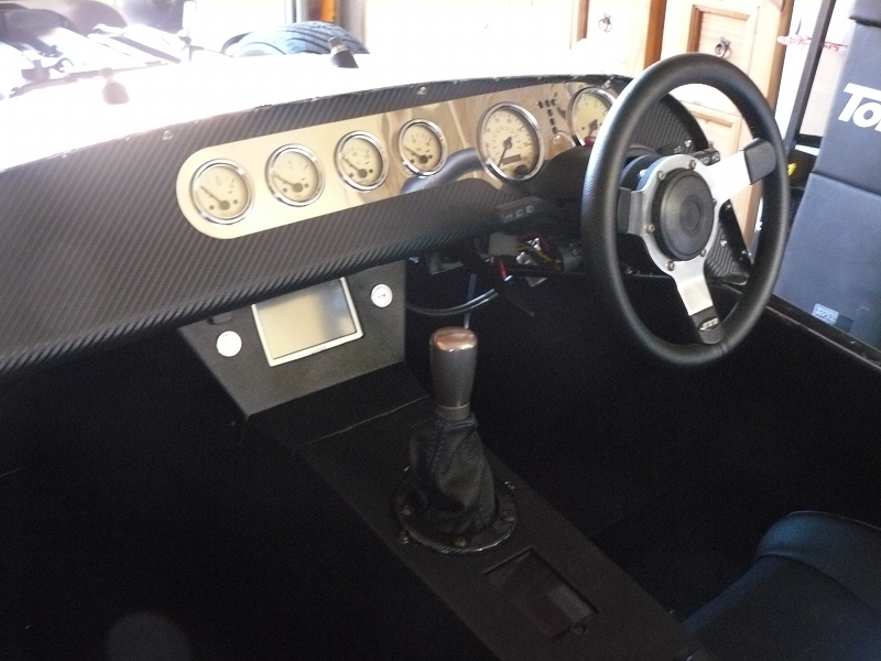
I just had to then see what it would look like fitted to the car.  Personally I think it looks pretty good.

Next job to tackle was the bonnet.  First I had to remove the exhaust manifold so I could trial fit the bonnet.  Now at this point I have to say that this is one of the things about the car I don't like.  The bonnet is rolled aluminium and really does not fit very well at all.  It will be better when it is all clamped down in place but at the moment it is pants!  When I tried pulling the sides in around the nose cone, there was a gap all the way round of between 5mm and 8mm and this just can't be correct.  Same around the scuttle.  Even with the sides pulled in tight, there are still gaps.  The picture below is without it pulled in tight, but you can get the drift.


I decided to walk away at this point as I didn't want to rush it and get it wrong.  It may be that it needs re-rolling and re-folding, but I don't have the tools to do that.  I am going to consult my son-in-law, who does body work and painting and get his help with it.  He may know someone who has the right tools to get the bonnet fitting correctly.  It would be a shame to ruin the car at this point with a badly fitting bonnet!  I will also consult the very knowledgable folk on the RHOCaR forum.

Saturday, 17 December 2011

Battery Tray And Dash

There hasn't been a lot of progress on the car for a few weeks as I have been busy gigging, but I had a rare Saturday off today so I decided to get some things done.

First job was to fit the battery tray panel.  I had already fitted the battery tray to the panel but had held off fitting it to the car until I was pretty sure I didn't need any access underneath it.  It was a simple task of lining it up and drilling some 3.2mm holes, de-burring and cleaning, laying a bead of silicone and fitting in place.  Here it is, job done.


Next I fitted the scuttle back on the car and started to bolt things on to it like the fuse box and the ECU.  It is all going to be a bit tight behind the dash so it will need a bit of careful thought as to where the wires are routed.  I had hoped the scuttle would now be finally fitted but I have a feeling it will need to come of again, or at least loosened to get the dash fitted.


Talking of the dash, I have been trying to decide on the final colour of the car and, accordingly, the dash colour.  My Son in Law has offered to paint the car for me but he is snowed under with work and family commitments so I don't feel now is a good time to be asking this favour of him.  I can always get it done another time.  Anyway, this means that I am going to leave the car white/aluminium but as I have gone for magnolia dials, I didn't think the dash would look right white as well.  Having seen a couple of others cars with carbon dashboards, I decided this was the way to go.

Now I wasn't about to spend £100 on a proper carbon dash when I have a perfectly good GRP one to work with.  I bought some 3M carbon covering and have used that.  The only other thing I had to buy was a hair dryer and that cost all of £8.99 from Tesco.

I cleaned up the GRP and set about laying on the carbon covering.  The flat surface was fine but doing the curved parts was more of a challenge.  This is where the hair dryer is invaluable.  You heat up the carbon covering and it turns in to a much more pliable material allowing it to be molded round the complex curves.  As it cools down it hardens up and retains the shape.  Below you can see me working my way round the back of the dash.


And here is the finished product, with the holes for the instruments and warning lights cut out.  There are still a couple of little bits to tidy up but this will all be hidden by the instruments and the  stainless trim.  I must say that I am pretty pleased with the finished result.


I thought I would just see what it would look like with the instruments fitted.  So here it is without the instrument surround.  It looks OK but I am not sure how I would deal with the T shaped hole for the warning light module.


And with the surround. This deals with the warning lights a lot better and would just end up with a proper T shaped cover for the warning lights that displays the little symbols with the right colours.


Talking of the warning lights, as you can see from the dash above, I have opted for the all in one T shaped lights.  I have also gone for the plug and play instrument loom from GBS.  The only problem was that there was a socket for the warning lights but no little loom to join it with.  A quick call to GBS and Ben came to the rescue.  I sent him the loom and the T module and he made me up a loom, and a nice job he made of it too.  It was all back to me within a week and all for a very reasonable cost.  Here is the instrument loom and the warning light loom.


So that is it for a couple of weeks now due to Christmas and New Year.  I am aiming to have the car ready to go to the factory for the IVA check over and then the test its self by the end of March.  Only time will tell if I can stick to that deadline.