Monday, 22 April 2013

On the Rollers

One of the things I have been waiting to do is to get the car on the rollers to see what BHP she has.  The local branch of the Westfield Sports Car Club (WSCC) had arranged a trip to visit Bradley's Garage, also known as BTEC Racing (http://www.btecracing.co.uk) to do an engine check and also a suspension set up check.  The garage is situated in the village of Shipton Under Wychwood in The Cotswolds, so it is a very nice place to have to get to ... well except for the pot holes in the road which I think we are all having to dodge around at the present time!!

The weather for the drive over wasn't too bad and at least the rain held off and I was there for about 11.00am.  There were a few cars already there but I didn't have to wait too long before it was my turn.  The front wheels were clamped in place with the rears on the actual rollers.


Here you can see the technician giving it some beans.  I have never been so nervous in my life as he revved the nuts out of my engine.  I kept waiting for it to go bang, but it didn't!!


Here is the result from run number 2 163.6 BHP @ 6067 rpm


Here is the result from run number 3 167.6 BHP @ 6182 rpm.


GBS had said that the standard 2.0 Zetec fitted with their plenum chamber should put out around 165 BHP so to get just shy of 168 BHP was very pleasing, especially as it is a bog standard engine.

On the basis that the car weighs 630 Kg (not the lightest of Sevens), that is around 265 BHP/tonne.

After the rolling road, I put the car on the ramp to have the alignment and geometry checked.  Now I have to be honest and say that this is all a bit of a dark art to me and all I really wanted to hear from the guys was that the set up was 'OK for the road' as I don't intend putting the car on the track, well not at the moment anyway.

So the strange thing on the steering wheel simply to set the it in the right position to measure where the wheels are pointing in relation to where it looks like I am pointing them, if that makes sense!


They then attached one of these units to each wheel and set about taking lots of measurements.


The net result is that it could do with a little bit of tweaking here and there but nothing massive and he did start talking about caster angles and toe in and degrees of this and degrees of that and I think I nodded in the right places so it looked like I understood.  I didn't really and when he said it is probably good enough for the road, I was happy.  I could book it in to them to tweak it, but it would end up costing me a lot and I am not convinced I am a good enough driver to really notice the difference.  Perhaps I will think about it one day.

Overall, it was a very enjoyable day even though I had to put the roof on to drive home as the rain had started to come down.  Oh well, you can't have it all!!!

Saturday, 9 March 2013

Quick Release Steering Wheel

A quick release steering wheel is a great anti-theft device, especially whilst the car is left out in the open or in an unfamiliar location.  I am planning on using the car a lot more this year (weather permitting), including a trip to France, so this seemed like an obvious security upgrade to make.

There are 2 types of quick release that you can fit.  One requires a splined shaft to be welded on to the existing steering column and the other is bolted on.  I opted for the latter.  All it takes is the kit and about 20 minutes of your time to fit.

This is the starting point.  First thing to do is remove the steering wheel from the original boss.


Here are the parts laid out.  It is a very simple mechanism, but it does the job.


Next job is to fit the steering wheel part (I can't think what else to call it!) to the steering wheel.   There are wires to enable a centre horn push to be fitted but as my horn button is separate, I didn't worry about these.  This is it from the front.


And this is it fitted from the back.  It is all held together with 6 Allen screws.


Next job is to fit the boss part (again, not sure what else to call it!) to the existing boss.  Again this is by way of 6 Allen bolts (supplied in the kit)


And finally, push the steering wheel in to the quick release and turn the securing ring and lock in to place.  Here is is fitted.


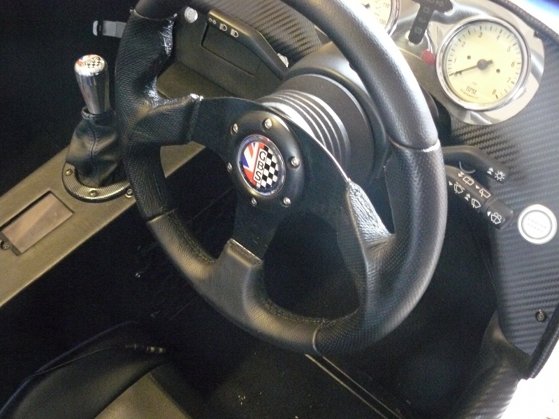
And another view.  You can see that it only bring the steering wheel closer to the driver by 25mm, it is the shallowest on the market.


All I need to do now is find a break in the weather to try it out!!

Sunday, 10 February 2013

iPod, Sat Nav or Both??

I managed to take the car out for a spin last weekend and had my 'in ears' (headphones) plugged in to the iPod as usual.  If you have read, or at least skimmed through, the blog you will know that I have built in the iPod and also built in the Sat Nav.


This is all well and good but when you are using the Sat Nav for directions, you can't hear the instructions over the music and the general noise in the car.  I needed to find a solution that wasn't going to cost me a lot of money and would give me the best of both worlds.

The first thing to consider was an all in one unit.  After a lot of research, the only Sat Nav unit I could find with a headphone socket that came close to what I wanted was the Garmin 2585TV which is a Sat Nav with TV tuner and can play MP3s etc.  However at £250 it was not really an option.  Anyway, I already have a Sat Nav and an Mp3 player so what is the point.  I needed a way of hearing the Sat Nav in my 'in ears' along with my music.

I decided that the only way was to get the soldering iron out and make up a one off cable to do the job.  Now first off, I must apologise that I didn't take any photos of the process, so my words will have to do.

I needed a mono out from the Sat Nav to link to a stereo out on the iPod to the stereo in on the 'in ears'. First job to tackle was the Sat Nav.  On YouTube you can find numerous videos of how to replace the battery on a Sat Nav and I used one of these to show me how to get in to the unit.  Once in, with it suitably dismantled, I unplugged the speaker plug from the circuit board and cut the wires.  I then soldered on some single core speaker wire.  I drilled a small hole in the outer casing of the Sat Nav for the cable to be passed through and set about putting it all back together.  This was an easier process than I thought it was going to be and within about 30 minutes the whole process was done.

Wiring up was straight forward.  Take a cable with a stereo plug for the iPod and cut one end of it off.  Each side will have an inner cable and an outer cable.  Twist and join the outer cable from both sides so you end up with a single outer, a single red and a single white cable.   Do the same with a cable to go to the 'in ears'.  Next join the red to the red, the white to the white and the out to the out on the 2 cables.  Check at this point that it is all working.  Finally add the left and the right from the Sat Nav cable to the red and the white of the combined cable and check again.  I now have music in stereo from the iPod and instructions over the top from the Sat Nav.  Finally solder all the joints, insulate and bind it all together with tape.  Job done.

Final job was to fit it all back in the car.  At the same time I took the opportunity to change the charger option for the Sat Nav so it uses a USB cable and not a hard wired cable.  This is so I can plug the Sat Nav in to a laptop for updates as they are required.  The iPod already has this type of cable so I can update the content without having to dismantle the car each time.

So there you go.  A simple job.  Total cost, including a new soldering iron, £20.  And it took about 3 hours total time including taking the car apart and putting it back together.  Just need to get the volume levels right on the road and for that, I need some more good weather to take the car out!!

UPDATE 17th Feb 2013

So, finally, a decent day to take the car out and see what the finished product is like.  I set off with neither iPod nor Sat Nav on, as neither had any charge in them, so I knew I needed a good run to put some charge in them.  At a convenient point, I pulled over and set about putting in the 'in ears' and switched on the Sat Nav.  First thing was it couldn't get a GPS signal.  That has worked in the past, but has never been 100%.  Anyway, I turned on the iPod and ..... nothing .... well a lot of static and nothing else.  Disappointed, I carried on on my journey and went home.

My wiring had worked on the bench, but the real world test had failed miserably.  I suspect it was a combination of the location of the Sat Nav and the fuse box and electricity etc causing the interference, which, of course, I didn't have on the bench.

So, the conclusion.  Unless you are some sort of electrical genius and understand these things and are prepared to spend some money on posh kit, stick with the Sat Nav mounted to the window!  It is now back to the way it was before for a while,and I think that is where it is going to stay. I have admitted defeat!!!

Saturday, 2 February 2013

Rear Suspension and other bits.

On to the rear suspension.  This is a lot more of a palaver than the fronts as access is a lot harder.  First thing is to remove the rear arches and store them out of the way.

Next is to gain access to the top mounting bolts.  Now on the first image below, you can see a nice little access hole to get at the top mounting bolt, and it is easy to get at with nothing else in the way.


 The problem was that I had added the boot panels and the access hole, where the clamp is in the picture, has now gone.

Add to this, I then covered it in carpet!!

To get access meant pulling back the carpet and going postal on the panel.  It is not a very neat job, but at least I have access.  I will use some Velcro so it gets put back in place but can be accessed later if needs be.

In fact it is so nasty I am ashamed to put up a picture of it!!

So, after all that faffing about, I finally got to fit the new DamperTech shocks.


Once fitted I lowered the car back to the floor and started to wind the shocks up to get the ride height right.  The rear needs to be between 130mm and 140mm to the bottom of the chassis rail just in front of the rear wheel arch.  As much as I wound up the springs, they weren't going over 120mm, which is just way too low for my driveway access, not to mention speed bumps.

So off they came.  You can see in the image below, that they are not far off, in fact only about 1/4 inch short, but that equates to quite a bit on the ride height.


Anyway, they had to go back to GBS to be sorted out.  They were really good about it all although with Christmas getting in the way, they did take a few weeks before they were returned to me.

I finally got round to fitting them and getting the car back together and also added a couple of other small parts.  The first was a new gear knob from GBS.


Next was a map pocket.


Then a phone holder.


And finally, a GoPro Hero 3 camera.  Here it is fitted tot he roll bar.


I decided it might be better hung under the roll bar.


You can just about make out the GoPro app on the phone which is used to control the camera and also acts as a view finder using a wi-fi connection.  All very clever.


Once all this was done, I was able to take the car out for a drive, the first in about 3 months.  The good thing is that I can feel a definite improvement with the suspension.  My fear was that, after such a long time getting them sorted, I might have forgotten what the old ones were like, but this was not the case.  I am not clever enough to say exactly why, but they just feel better.  The ride is smoother and they seem to absorbs the bumps better.  That is the best way I can describe them.

Anyway, I hope to new continue the blog but for it to be more of a drive blog than a build blog.  Roll on the better weather!!

Monday, 7 January 2013

Winter Upgrades - Electrics and Front Suspension

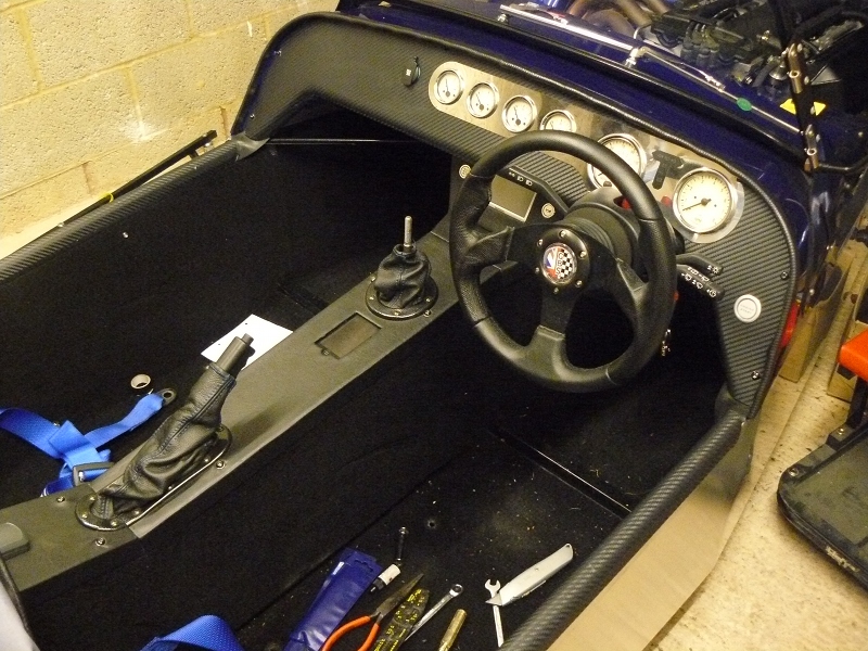
Next step in the winter upgrades is to move on to other little electrical jobs.  To get access to everything I wanted to get at, the first job was to take the interior apart.  I started by taking the tunnel top off to get at the speedo sensor, and then the switch/Sat Nav housing and that led to removing the dashboard and before you know it, it ends up like this!


One of the jobs I wanted to do was to wire up the savage switches so that they illuminate with the side lights on.  This means wiring the centre 2 connectors, one is the +ve (A on the switch) and the other -ve (B on the switch), so you have to make sure which is which.  I used a volt metre to find a spare pin on the plug from the main loom that was live with the side lights and wired a simple circuit.


These are not brilliant images, but these are the switches lit up.


Whilst the dashboard was out, I decided to move the 12v socket from the lower mounting point, where the access was very restricted, up to on the dashboard.  The was a simple job of finding the right place, masking up the dash and drilling the right size hole with a stepped drill bit.  Here it is fitted on the inside.


An this is it from the front.  It was a simple wiring job with the +ve coming straight from the battery with an in-line fuse and the negative to a chassis ground.  This way it can be used to trickle charge the battery or be used without needing to switch on the ignition.


One of the other jobs I wanted to do with car stripped out was have a look at re-positioning the speedo sensor.  The issue I have is that when I get to about 65mph, the speedo becomes very erratic and I am not sure how accurate it is.  I am relying on the Sat Nav to keep me to the speed limits, which is not good.  I originally positioned the sensor over 2 magnets on the differential flange.  That had its own issues as when I got to about 70, the speedo jumped to 120!  So I changed it so it looks at the bolt heads where the propshaft bolts to the diff, but looking at the side of the bolt heads.

I had done quite a bit of research on this subject and found that there isn't really a preferred method for triggering the sensor, only to make sure that the gap between the sensor and the bolt heads is between 1mm and 2mm. It also suggested that the sensor should point at the flat head of the bolts, not the sides.  With the set up I have I have no option but to point the sensor at the side of the bolt head so I made sure as best I could that as the bolt head passed the sensor, it was looking at a flat side and not one of the angles (if that makes sense).  I then positioned the sensor at 1mm and made sure that LED lit up as each of the 4 bolt heads passed the sensor.  Once the car is back on the road, I can see if it has made any improvement.  I am not sure what I will do if it hasn't improved.

Now she is going back together.


Next was to fit the front suspension units.  These were a simple swap from the GAZ units to these newer DamperTech units.


Yes, it is fitted upside down, but they are designed so that they can be run this way.  This fitment is also required to gain access to the adjuster valves, seen at the bottom of the unit.

Once these were fitted, I was able to fit the new Dominator headlamps.  They may be a bit small for some people, but I like them better than the large lamps that were on there before.


Here is the finished front end.


Just the rears to do now, then put it back together and start tweaking with the settings to get it right for the road.

Friday, 9 November 2012

The Upgrades Begin - Lighting

Since the last post, I have had presents!! The first parts to turn up were the Dominator headlamps.  I like the look of these smaller 4 inch units as opposed to 7 inch ones which I think are just a little too big.  This is all subjective, of course, and other people may disagree.  Hey, that is fine, it is what makes our cars so unique.

The next arrival was the mini indicators (not from a Mini but mini in size).  Here are the items laid out ready for fitting.


The next items to arrive were the new shock absorbers (or dampers).  These are the new ones that have been designed by GBS, working with Dampertech (www.dampertech.co.uk).  They are nitron filled and look the mutts!!


Anyway, I had a rare day off work and as the weather wasn't really conducive to a drive, I thought I may as well get on with the upgrades.  First job of the day way to get some head light markings from the old lights, so I would have something to line up the new ones with.  This was a simple task of shining the dip beam pattern on to the garage door and then put some masking tape where the line of the beams are.  This will at least give me a good starting point for the new lights.  I can take the car to get the lights properly aligned later.

So it was off with the bonnet and the nose cone first.


Then it was off with the old 7 inch lights.


I wanted to make use of the existing wiring loom as this included headlight and side light wiring.  It was a simple task of removing it from one light unit and adding it to the next.  It took a couple of attempts to get it right as far as the 4 way connector to the loom was concerned.  I initially only had main beam and nothing else, but a quick look at the GBS wiring diagram and I was on the right track, but not before I had blown the side light bulb!  A quick trip to the local motor factors and that was sorted.  I plugged the new light in and checked all the lighting functions and as they say, the jobs a good 'un.  I then repeated the process for the other side.  I won't actually fit the lights on to the car until some other jobs have been completed.  It stops them being knocked and also help with access.

I then moved on to the front indicators.  First job was to remove the old indicators.  This is when I noticed that there was some slight cracking and crazing in the fibreglass where they were fitted.  I think this is caused by the extra weight they carry and the extension bars causing them to bounce up and down a bit.  Not a lot I can do about this without having the nose cone repaired and re-painted, and that is not possible at the present time.

When fitting the new, very light weight, smaller units, I added a couple of penny washers either side of the fibreglass to add some extra support.  You can just see one in the image below and you can see that I have sprayed it blue so it is less obvious.  You can also see how much smaller these units are.  


Here are both fitted.


Final job was to finish the wiring inside the nose cone.  This was a simple job of joining 2 wires, solder and wrap in tape.


Final job of the day was to plug in the wires to make sure they worked OK, which I am happy to say, they did.  Again, the nose cone won't be put back on the car until other jobs have been completed.

Monday, 5 November 2012

Winter Upgrade Plans

I think it is fair to say that a kit car is never really finished.  It may get to a point that you are happy with it, but is it really finished?  My car has been on the road for 7 months now and I have covered just over 1300 miles.  In that time, I have had to replace the exhaust (which has been covered in an earlier post) and also replaced a fuel pump and fuel filter, following some fuel starvation/dirt issues.

When I built the car, I had to build it to the IVA rules.  That is now a thing of the past, so I can start to change things.  I didn't want to take the car off the road in the summer (well, what summer we had) but now, as the winter months approach, I am planning to make some changes.

So what is being planned and why?

1.  New shock absorbers - I would like to be able to fine tune the suspension a bit better and try and get a more production car type ride, which I just don't think is possible on the GAZ shocks that came with the starter kit.

2.  Re-Shim the rear suspension - When the car went through the IVA, it was pointed out to me that I needed to add some extra shims (washers) in to the rear suspension, so whilst I am replacing the shock absorbers, I might as well do the shims.

3.  Head Lamps - The 7 inch lights are a little too big for my liking so I am going to fit smaller units

4.  Front Indicators - I had to fit larger indicators and extension bars to pass the IVA test, I would now like some smaller units.

5.  Quick Release Steering Wheel - I like the idea of one of these for extra security if I take the car away from home, especially as I am hoping to take it abroad.

6.  Finish wiring the Savage switches - I never got round to wiring in the lights on these switches so at night they light up.

7.  Get speedo working correctly - I have never been happy with the speedo sensor so I am going to try and get it working correctly.  There are a few option to how I might do this.

I have a few other ideas of things I would like to do, but I haven't decided fully on them yet so I won't mention them in case they don't come off.

So there we go, that should keep me busy for a few weeks.  First thing to do is to start ordering the parts I need and then start to take the car apart.  I just want to leave it a bit longer, just in case we have a warm spell and I can get another couple of blasts out in her before the work starts.  Yeah, who am I kidding!!!